Few would argue that fin-tube baseboard was the “flagship” heat emitter in North American hydronic heating systems through much of the 20th century. Its origins go back to the 1930s, where it represented radical departure from the status quo of cast-iron radiators. Since then, it has maintained its place in residential hydronic systems, despite the fact that its fundamental construction hasn’t changed much.
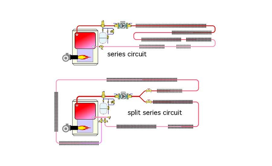
A typical residential fin-tube baseboard system connected multiple baseboards into either series or “split series” circuits, as shown in Figure 1.
In many systems, the fin-tube elements in the baseboards used 3/4-inch copper tubing. Baseboard elements were connected by soldering lots of copper elbows to short “stubs” of copper tubing. These piping assemblies routed flow down through the floor deck, and offset it horizontally to account for wider foundation walls, relative to the typical 2x4 studs used in many 20th century homes. It was common to use eight 90-degree soldered copper elbows to connect each baseboard in such systems.
Much of that soldering had to take place in the cramped spaces, between floor joists and above foundation walls. The joints were often made in close proximity to wood, as evidenced by plenty of “char scars,” which to me, scream of unprofessional workmanship. Lots of time was required to measure, cut, ream, clean, flux, solder and wipe all those joints.
Once these series or split-series systems were put into operation, there wasn’t much that could be done to adjust heat output on a room by room basis. It was not uncommon to hear complaints that the heat output in the room at the end of a series baseboard circuit was a bit “light.” This was usually caused by sizing the baseboards based on the average water temperature in the circuit, rather than the actual inlet temperature at each baseboard.
SO LONG SERIES
There weren’t many choices for materials when fin-tube baseboard was the standard for residential hydronic heating. Most installers just soldered 3/4-inch copper tubing, elbows and baseboard elements together to form series circuits. Some used diverter tees to allow some of the baseboards to be bypassed. The latter technique could be used to limit heat output of each baseboard — provided some type of valve was installed in each branch piping path.
However, it still didn’t allow each baseboard to independently call for heat. It also suffered from the same sequential temperature drop characteristic associated with any circuit with series-connected heat emitters. Parallel piping methods, such as “2-pipe” reverse return, were understood by mechanical system engineers and often used on commercial fin-tube applications, but seldom applied in residential systems.
The arrival of PEX tubing in North America in the early 1980s did not immediately affect how fin-tube baseboard was installed. When first introduced to North America, PEX was viewed with a degree of skepticism by many heating pros who had spent years working with rigid metal pipe. I know because I was one of them.
Eventually, I decided to try PEX tubing on a radiant slab project. It was for an addition at my church. Although I generally felt that the congregation had faith in my decision, I still recall discussions of how Siggy was burying “garden hose” in the floor to heat the new addition. Thirty-two years later, that tubing is still working great, and several other projects at the church have all incorporated PEX tubing floor heating.
Today, most heating pros view PEX, or similar tubing such as PEX-AL-PEX or PE-RT as a “universal” hydronic tubing. They have confidence that it can work in a wide variety of systems, including many types of radiant panels as well as with panel radiators, fan-coils and even fin-tube baseboard.
PARALLEL PRAISES
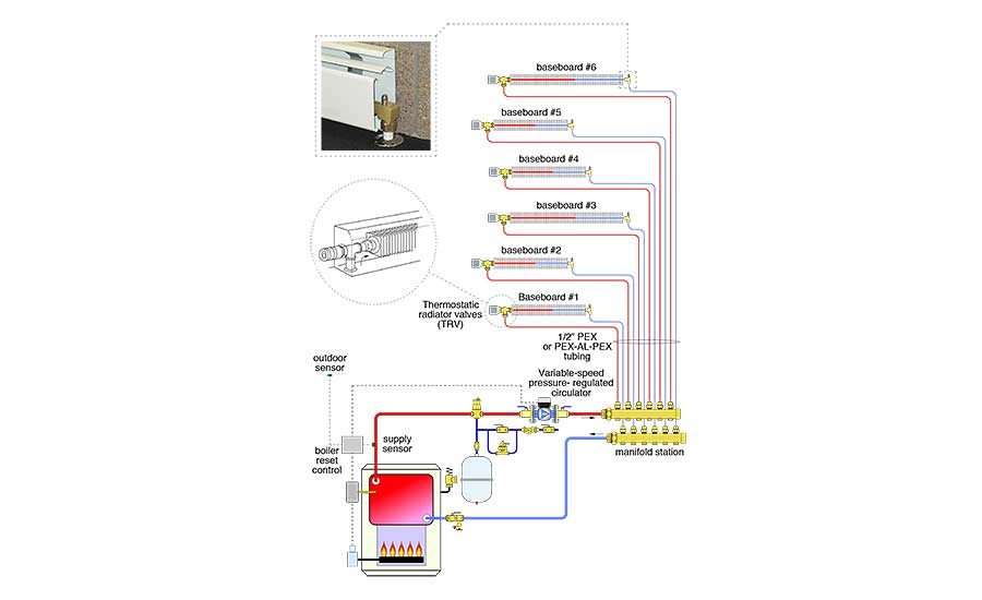
PEX tubing makes it possible to connect fin-tube baseboards in parallel rather than series. Figure 2 shows this concept as a “homerun” distribution system.
Each baseboard has two 1/2-inch PEX tubes routed to it from a central manifold station. That tubing can be easily pulled through holes in floor framing or up through studded walls. In most cases, there are no joints in the PEX tubing between the manifold station and the baseboard.
The parallel piping circuits provide several benefits that are not possible with series piping. First, each baseboard receives essentially the same supply water temperature. The sequential temperature drop associated with series piping or diverter tee systems is eliminated. This makes it easier to size the baseboards to their respective room heating loads.
Second, it’s possible to regulate flow rate through each parallel circuit. This can be done using valves built into the manifold station, or with valves at each baseboard.
Third, even though it’s possible to operate all parallel circuits as a single zone, it’s very easy to go one step further and set up each baseboard up as an independently controlled zone.
WIRED OR “WIRELESS”
Flow through each baseboard can be controlled using “wireless” thermostatic radiator valves mounted at the inlet of each baseboard, as shown in Figure 2. No wires, no batteries, just simple, reliable and accurate room comfort control.
Another option is to mount the radiator valve and actuator head inside the baseboard enclosure, or under the floor, and use a remote setting dial connected to the valve’s actuator head by a capillary tube. This is nice in situations where occupants don’t want to bend over to adjust the room comfort setting.
If electrical thermostats are preferred, just mount 24VAC valve actuators on the manifold station and connect them to the thermostats using a multi-zone relay center.
When the system being zoned uses a variable-speed pressure-regulated circulator, set it for constant differential pressure operation. As the thermostatic radiator valves or manifold valve actuators open and close, the circulator auto-matically ramps its speed up and down to keep the flow rate in each parallel branch nearly constant. This type of circula-tor also eliminates the need for a differential pressure bypass valve, and significantly reduces electrical power consump-tion relative to fixed speed circulators.
FLAMELESS
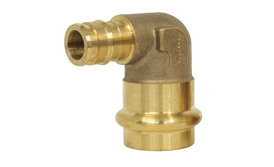
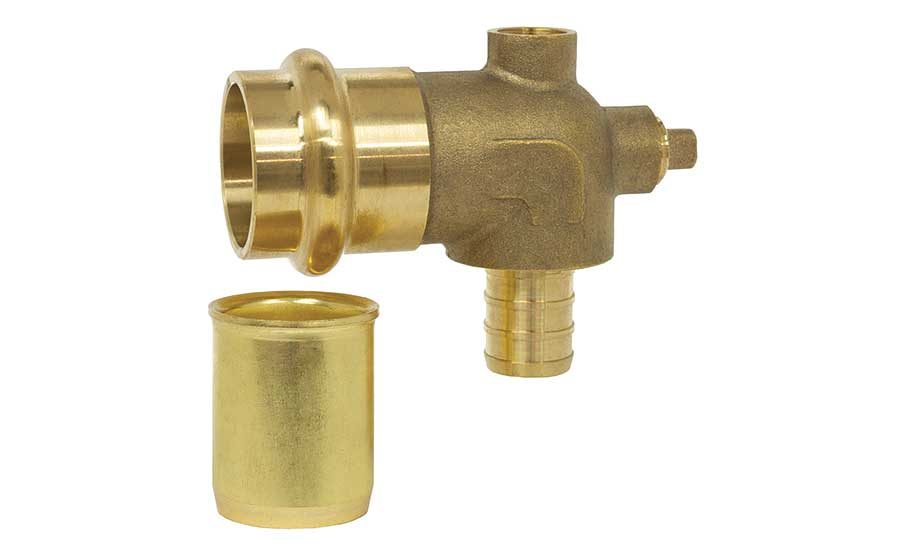
It’s now possible to connect PEX tubing to the copper tubing in a baseboard element without soldering the latter. Figure 3 shows two fittings designed for this purpose.
The elbow in Figure 3a transitions from an ASTM F1960 “cold expansion” connection on 1/2-inch PEX tubing to a press connection on 3/4-inch copper tubing. The fitting in Figure 3b transitions from an ASTM F1807 crimp connection for 1/2-inch PEX tubing to a press connection on 3/4-inch copper. This fitting also has two 1/8-inch FPT tappings, one of which can be used for an air vent. The other is simply plugged.
The brass sleeve shown in Figure 3b is a tube stiffener that allows a press connection on the thin wall copper tubing used in modern fin-tube baseboard. Both of these fittings are ideal for “flameless” connections to fin-tube baseboard. No more char marks or messing around with multiple copper elbows and short tube stubs in those tight confines between floor joists.
From a single zone series circuit constructed using 100-plus solder joints to multi-zone systems using zero soldered joints and low power variable speed circulators, the methods and materials available for installing fin-tube baseboard have come a long way in the last few years. Are you taking full advantage of them?


